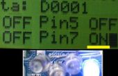
Paso 4: El programa de demostración de
Iniciar el IDE de Arduino y copiar/pegar este programa en él. Sube el programa a la Attiny85.
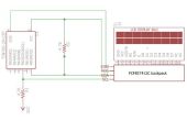
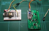
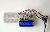
/********************************************************************* * Filename LCDdemo.ino * * Print "Hello World!" on the first line, * then count seconds on the second line. * * On the side of the shield with the buttons and the chip there are * two sets of six pins. Looking at the shield with the reset button * on the right there are 12 pins. We will call them 1 - 12 from left to right. * Pin 3 connects to the positive rail. * Pin 5 connects to the ground rail. * Pin 11 connects to digital pin 0 on the Attiny85. * Pin 12 connects to digital pin 2 on the Attiny85. * ********************************************************************/ #include <TinyWireM.h> // ATtiny I2C communication #include <TinyAdafruit_RGBLCDShield.h> // RGB LCD Shield communications Adafruit_RGBLCDShield lcd = Adafruit_RGBLCDShield(); long secs = 0; void setup() { lcd.begin(16, 2); // set up the LCD's number of columns and rows. lcd.setBacklight(7); // For monochrome LCD lcd.setBacklight(ON) lcd.clear(); lcd.setCursor(0,0); lcd.print("Hello World!"); } void loop() { lcd.setCursor(0,1); lcd.print(secs); delay(1000); secs++; } La línea de código que dice "lcd.setBacklight(7);" es para un LCD RGB. Puede utilizar los números 1-7 para establecer la backilght en diversos colores. Si está utilizando una pantalla monocromática que uso "lcd.setBacklight(ON)";.
