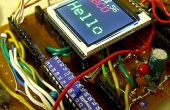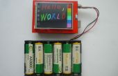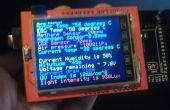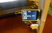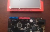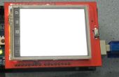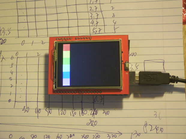
Recientemente estoy experimentando 2.4" TFT LCD Display con Arduino, compré el LCD no previsto hacer algo pero solo quiero saber si funciona o no. He buscado el instructables, youtube pero un montón de código no funcionaba, así que proceder un estudio intensivo de caso para comprobar por qué, tal vez mi versión de tarjeta difiere, empiezo a modificar el código existente y finalmente consiguió un gran avance y esperemos que puede resaltar a aquellos otros que están enfrentando el mismo problema.
El nombre original de código llamado tftpaint.ino, una simple búsqueda en Internet pueden encontrar fácilmente, sólo destacando los cambios que hice aquí para conseguir trabajo.
1. código han utilizado la biblioteca de SWTFT.h no funciona en mi tablero, cambiar a Adafruit_TFTLCD.h.
2. corregir las clavijas de define como
#define YP A3 / / debe ser un pin analógico, utilice "Una" notación!
#define A2 XM / / debe ser un pin analógico, utilice "Una" notación!
#define 9 YM / / puede ser un pin digital
#define XP 8 / / puede ser un pin digital
3. volver a asignado el punto de anclaje de bloques de color, aparente las coordenadas XY de mi tablero se diferencian
tft.fillRect (PACKINGCOLORTAMAÑO * PACKINGCOLORTAMAÑO 5, * 0, PACKINGCOLORTAMAÑO, PACKINGCOLORTAMAÑO, rojo);
tft.fillRect (PACKINGCOLORTAMAÑO * PACKINGCOLORTAMAÑO 4, * 0, PACKINGCOLORTAMAÑO, PACKINGCOLORTAMAÑO, amarillo);
tft.fillRect (PACKINGCOLORTAMAÑO * PACKINGCOLORTAMAÑO 3, * 0, PACKINGCOLORTAMAÑO, PACKINGCOLORTAMAÑO, verde);
tft.fillRect (PACKINGCOLORTAMAÑO * PACKINGCOLORTAMAÑO 2, * 0, PACKINGCOLORTAMAÑO PACKINGCOLORTAMAÑO, cian);
tft.fillRect (PACKINGCOLORTAMAÑO * 1, PACKINGCOLORTAMAÑO * 0, PACKINGCOLORTAMAÑO, PACKINGCOLORTAMAÑO, azul);
tft.fillRect (PACKINGCOLORTAMAÑO * PACKINGCOLORTAMAÑO 0, * 0, PACKINGCOLORTAMAÑO, PACKINGCOLORTAMAÑO, MAGENTA);
