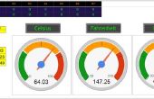
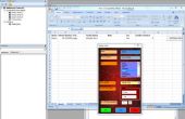
Paso 6: Instrucciones generales
Aquí están algunas instrucciones generales que puede también ser encontrado en los comentarios del código:
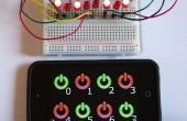
////////////////////////////////////////////////////////////////////////// Instructions ///////////////////////////////////////////////////////////////////////////////// // This is a simple example processing script that allows users to easily create // Graphical User Interface (GUI) widgets with simple connections to an arduino. // It uses the Fermata library to establish the connections between Processing and Arduino. // It's also a simple introduction to both object oriented and windows type UI coding and event handling. // The current implementation is pretty lean graphically, partly in order to make the code legible, editable and instructive. // // To use: on the Arduino side upload the StandardFermata code found under Examples->Fermata in the Arduinoi development environment // // There are currently (5) types of ArdWidgets: // - a pushbutton ArdWidgetButton // - a horizontal and vertical slider ArdWidgetHSlider and ArdWidgetVSlider // - a two dimensional ArdWidgetXY widget that can drive two arduino pins // - an extensible ArdWidgetGraph that can take an arbitrary number of INPUTs and OUTPUTs and graph values over time // // The ArdWidgetButton is a Digital UI element that reads or drives digital arduino pins // The ArdWidgetSliders, ArdWidgetXY and ArdWidgetGraph read or drive analog pins and produce analog (0-255 or 0-1023) values // // The basic signature of creating a widget is pretty consistent: // ArdWidgetXXXXXX ( int x, int y, int w, int h, int anio, int apin) // x, y, w, and h are standard for many processing elements, respectively the X and Y origin of the widget // and the Width and Height. // These define the rectangular region the widget will take on the canvas // // io is either INPUT or OUTPUT. These are the same meaning as for the Arduino // OUTPUT widgets will write values to output pins (analog or digital). // They drive user interaction to phyical outputs on the Arduino // INPUT widgets will display the values read from analog or digital pins to Processing; // these display but do not respond to mouse interactions // // Finally, apin is the pin number to be read or controlled by the widget. Note that: // Digital widgets (ArdWidgetButton) read or write one of the digital pins numbered 0 - 13. // Analog OUTPUT widgets must have one of the analog output pins specified, // indicated on the arduino with a ~ (pins ~3,~5,~6,~9,~10,~11) // Analog INPUT widgets use the analog input pins, and accept inputs from 0-6. 0 corresponds to pin A0, etc. // the ArdWidgetXY and ArdWidgetGraph creation call is different from the others in that they require an array of pins, // and the graphwidget takes an array of ios: // ArdWidgetXY ( int x, int y, int w, int h, int anio, int pin, int pin2) // // There is also a basic ArdWidgetsCollection class that ArdWidgets are added to and handles messaging, // mouse events, etc. // // The example setup() routine below shows how to create the different types of INPUT and OUTPUT widgets // and add them to Processing. // // Send comments and feedback to dshelden
