Paso 8: UPCB Cable
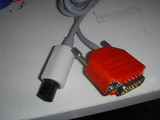
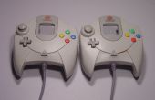
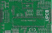
DREAMCAST Looking at controller end that plugs into the Dreamcast ___________ | 5 3 1 | \ 4 2 / --------- Pin Description Standard Wire Color 1 Serial A red 2 +5v blue 3 GND black 4 sense green 5 Serial B white Line 4, 'sense', is connected to ground in the controller. The Dreamcast uses this line to detect when there is a controller in place. Since we can connect it to ground inside the UPCB console cable hood, there is no need to connect this to the UPCB itself. To make a UPCB cable for the Dreamcast Piggyback, match up pins like this: D-Sub 15 Pin GC Pin 1 3 (GND) 2 Low 3 Low 4 High 5 High 6 Low 7 Low 8 2 (+5v) 9 NC - Not connected to anything 10 High 11 High 12 NC - Not connected to anything 13 1 (Serial A) 14 5 (Serial B) 15 Low You'll want to also solder in the 'sense' line to any one of the 'Low' lines. I soldered mine into 15 along with the little jumper wire that connected it to the rest of the 'Low' lines.
Cableado hasta el Dreamcast Piggyback cable no es diferente del cableado hasta cualquier otro cable UPCB. Conectar todos los pines de alta y baja, luego conecte los cables del cable sí mismo, y ya está. Por favor consulte el Instructables otros dos en la fabricación de un cable UPCB:
Cómo construir un cable de consola para el PCB Universal.
