Estoy escribiendo esto por lo que puedo recordar cómo hacer este último. Se trata de un hack tirado unos años atrás y sólo salen del armario para volver a utilizar.
ANTECEDENTES
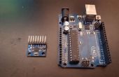
Es común que desea guardar los datos de un acelerómetro con un dispositivo que es pequeño. Estoy utilizando dos tablas de la diversión de la chispa; Abra el registro y desglose de MMA8452 (es decir el acelerómetro, como en el teléfono inteligente).
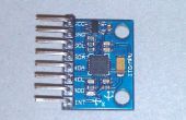
El MMA8452 breakout es un acelerómetro de 3 ejes barato montado en un tablero de circuito pequeño. La cabecera incluye los pines de comunicación (I2C (creo)). Hay ejemplos de cómo conectar y usar esto con una placa de desarrollo arduino.
IDEA
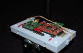
Los tableros de registro abierto es básicamente un arduino con una ranura para tarjeta microSD adjunta. El arduino recibe serie de datos de las líneas de TX/RX y guarda esto en la tarjeta microSD. Los pernos traídos hacia fuera de la cabecera son justo lo que necesitas colocar a un arduino mini - para que el uso previsto es utilizar esto para leer algunas salida de otro circuito de arduino.
CABLES DE
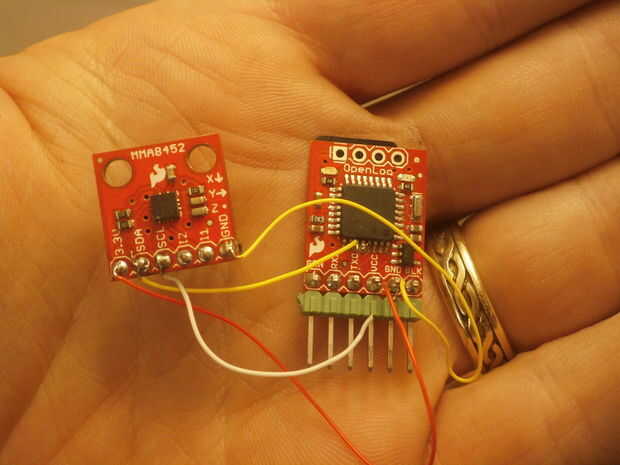
Así que si sólo quieres leer y guardar los datos del acelerómetro, tiene sentido para conectar directamente con el registrador de datos. Sólo tienes que averiguar que alfileres ir donde...
MMA8452: OpenLog(atmega328) equivalente pin utilizando el IDE de Arduino
3.3V---Vcc de cabecera
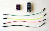
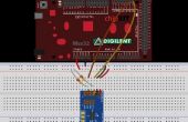
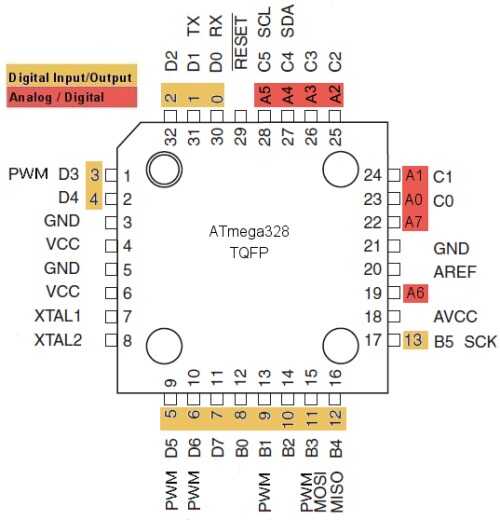
SDA---Pin 27 atmega 328---A4 (amarillo alambre en foto)
SCL---Pin 28 en atmega 328---A5 (cable en foto blanco)
TIERRA---GND
Nota: de diagrama de pines de arduino http://forum.arduino.cc/index.php?topic=132130.0
atmegaTQFP
El registro abierto con un 3, 3V del programa básico de FTDI. La mayoría de las clavijas Conecte directamente de cabecera a cabecera--excepto que necesita cambiar las líneas de TX/RX. Así que OpenLogTXO va a FTDI_RXI.
Aquí está el cableado
FTDI OpenLog Basic
NEGRO---NEGRO
TIERRA---GND
VCC---3.3V
TXO---RXI (no directamente a través de)
RXI---TXO (no estrecho a través de)
TIERRA---GND
no utilizado---negro
CÓDIGO de biblioteca que necesita-
Necesita la biblioteca por el acelerómetro:
https://github.com/Sparkfun/MMA8452_Accelerometer/...
Coloque el archivo en el archivo de las bibliotecas en el directorio sketchbook. Para encontrar el libro para dibujar, en arduino IDE, seleccione Archivo -> Preferencias y es justo en la parte superior. Luego cierre arduino IDE y abrir.
(mucha información aquí:)
https://Learn.Sparkfun.com/tutorials/mma8452q-acce...
CÓDIGO - escribe acelerómetro salida a la tarjeta SD.
Hay algunos muy buen código para su uso con el registrador de abierto, le permitirá cambiar los parámetros y hacer nuevos archivos, no estoy utilizando ahora mismo. Simplemente añadir la tarjeta SD al ejemplo básico del acelerometro. Esto tiene captura - que debe ser archivo llamado datalog.txt en la tarjeta SD. Es el archivo de a que los datos se van.
El código debe ser fijado.
Se llama: MMA8452_Plus_SDLogger
ENLACES:
https://github.com/Sparkfun/MMA8452_Accelerometer
https://github.com/Sparkfun/openlog
NOTA:
el código no se subirlo... así que aquí está como texto.
código registrador acelerómetro más datos / / /
modificado por MPC Marc Cryan / / /
/* MMA8452Q Basic Example Code Nathan Seidle SparkFun Electronics November 5, 2012 License: This code is public domain but you buy me a beer if you use this and we meet someday (Beerware license). This example code shows how to read the X/Y/Z accelerations and basic functions of the MMA5842. It leaves out all the neat features this IC is capable of (tap, orientation, and inerrupts) and just displays X/Y/Z. See the advanced example code to see more features. Hardware setup: MMA8452 Breakout ------------ Arduino 3.3V --------------------- 3.3V SDA -------^^(330)^^------- A4 SCL -------^^(330)^^------- A5 GND ---------------------- GND The MMA8452 is 3.3V so we recommend using 330 or 1k resistors between a 5V Arduino and the MMA8452 breakout. The MMA8452 has built in pull-up resistors for I2C so you do not need additional pull-ups. */ #include <Wire.h> // Used for I2C// The SparkFun breakout board defaults to 1, set to 0 if SA0 jumper on the bottom of the board is set #define MMA8452_ADDRESS 0x1D // 0x1D if SA0 is high, 0x1C if low//Define a few of the registers that we will be accessing on the MMA8452 #define OUT_X_MSB 0x01 #define XYZ_DATA_CFG 0x0E #define WHO_AM_I 0x0D #define CTRL_REG1 0x2A #define GSCALE 2 // Sets full-scale range to +/-2, 4, or 8g. Used to calc real g values./////////datalogger #include <SD.h> // On the Ethernet Shield, CS is pin 4. Note that even if it's not// used as the CS pin, the hardware CS pin (10 on most Arduino boards,// 53 on the Mega) must be left as an output or the SD library// functions will not work.constint chipSelect = 10; /////////////////voidsetup() { Serial.begin(57600); Serial.println("MMA8452 Basic Example"); Wire.begin(); //Join the bus as a master initMMA8452(); //Test and intialize the MMA8452 ////////////SDLogger Serial.print("Initializing SD card..."); // make sure that the default chip select pin is set to // output, even if you don't use it: pinMode(10, OUTPUT); // see if the card is present and can be initialized: if (!SD.begin(chipSelect)) { Serial.println("Card failed, or not present"); // don't do anything more: return; } Serial.println("card initialized."); ///////////////////// } voidloop() { int accelCount[3]; // Stores the 12-bit signed value readAccelData(accelCount); // Read the x/y/z adc values // Now we'll calculate the accleration value into actual g's float accelG[3]; // Stores the real accel value in g's for (int i = 0 ; i < 3 ; i++) { accelG[i] = (float) accelCount[i] / ((1<<12)/(2*GSCALE)); // get actual g value, this depends on scale being set } // Print out values for (int i = 0 ; i < 3 ; i++) { Serial.print(accelG[i], 4); // Print g values Serial.print("\t"); // tabs in between axes } Serial.println(); ///////////data to SD card // open the file. note that only one file can be open at a time, // so you have to close this one before opening another. File dataFile = SD.open("datalog.txt", FILE_WRITE); // if the file is available, write to it: if (dataFile) { for (int i = 0 ; i < 3 ; i++) { dataFile.print(accelG[i], 4); // Print g values dataFile.print("\t"); // tabs in between axes dataFile.close(); } } // if the file isn't open, pop up an error: else { Serial.println("error opening datalog.txt"); } ////////////// delay(10); // Delay here for visibility } void readAccelData(int *destination) { byte rawData[6]; // x/y/z accel register data stored here readRegisters(OUT_X_MSB, 6, rawData); // Read the six raw data registers into data array // Loop to calculate 12-bit ADC and g value for each axis for(int i = 0; i < 3 ; i++) { int gCount = (rawData[i*2] << 8) | rawData[(i*2)+1]; //Combine the two 8 bit registers into one 12-bit number gCount >>= 4; //The registers are left align, here we right align the 12-bit integer // If the number is negative, we have to make it so manually (no 12-bit data type) if (rawData[i*2] > 0x7F) { gCount = ~gCount + 1; gCount *= -1; // Transform into negative 2's complement # } destination[i] = gCount; //Record this gCount into the 3 int array } } // Initialize the MMA8452 registers // See the many application notes for more info on setting all of these registers:// http://www.freescale.com/webapp/sps/site/prod_summary.jsp?code=MMA8452Qvoid initMMA8452() { byte c = readRegister(WHO_AM_I); // Read WHO_AM_I register if (c == 0x2A) // WHO_AM_I should always be 0x2A { Serial.println("MMA8452Q is online..."); } else { Serial.print("Could not connect to MMA8452Q: 0x"); Serial.println(c, HEX); while(1) ; // Loop forever if communication doesn't happen } MMA8452Standby(); // Must be in standby to change registers // Set up the full scale range to 2, 4, or 8g. byte fsr = GSCALE; if(fsr > 8) fsr = 8; //Easy error check fsr >>= 2; // Neat trick, see page 22. 00 = 2G, 01 = 4A, 10 = 8G writeRegister(XYZ_DATA_CFG, fsr); //The default data rate is 800Hz and we don't modify it in this example code MMA8452Active(); // Set to active to start reading } // Sets the MMA8452 to standby mode. It must be in standby to change most register settingsvoid MMA8452Standby() { byte c = readRegister(CTRL_REG1); writeRegister(CTRL_REG1, c & ~(0x01)); //Clear the active bit to go into standby } // Sets the MMA8452 to active mode. Needs to be in this mode to output datavoid MMA8452Active() { byte c = readRegister(CTRL_REG1); writeRegister(CTRL_REG1, c | 0x01); //Set the active bit to begin detection } // Read bytesToRead sequentially, starting at addressToRead into the dest byte arrayvoid readRegisters(byte addressToRead, int bytesToRead, byte * dest) { Wire.beginTransmission(MMA8452_ADDRESS); Wire.write(addressToRead); Wire.endTransmission(false); //endTransmission but keep the connection active Wire.requestFrom(MMA8452_ADDRESS, bytesToRead); //Ask for bytes, once done, bus is released by default while(Wire.available() < bytesToRead); //Hang out until we get the # of bytes we expect for(int x = 0 ; x < bytesToRead ; x++) dest[x] = Wire.read(); } // Read a single byte from addressToRead and return it as a bytebyte readRegister(byte addressToRead) { Wire.beginTransmission(MMA8452_ADDRESS); Wire.write(addressToRead); Wire.endTransmission(false); //endTransmission but keep the connection active Wire.requestFrom(MMA8452_ADDRESS, 1); //Ask for 1 byte, once done, bus is released by default while(!Wire.available()) ; //Wait for the data to come back returnWire.read(); //Return this one byte } // Writes a single byte (dataToWrite) into addressToWritevoid writeRegister(byte addressToWrite, byte dataToWrite) { Wire.beginTransmission(MMA8452_ADDRESS); Wire.write(addressToWrite); Wire.write(dataToWrite); Wire.endTransmission(); //Stop transmitting }
