Paso 3: programación
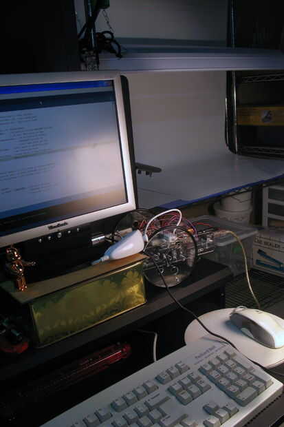
(muchas gracias a chad en windmeadow.com para hacer la investigación y la escritura muy fácilmente entendían código de Arduino para interactuar con el nunchuck de la Wii, el programa incluye su código prácticamente sin cambios).
Lo que hace
- El programa por defecto utilizando el nunchucks joystick para el control. Si se empuja la palanca hacia adelante tu robot irá hacia adelante, atrás, hacia atrás y así sucesivamente.
- Si mantiene pulsada la tecla "Z" (uno grande en el frente). Tu robot se moverá ahora basado en la inclinación de la nunchuck. Inclinación hacia adelante para seguir adelante...
- Finalmente si bien todavía no funciona el programa enviará el estado de los botones de nunchucks, joystick y acelerómetros, cada segundo sobre puerto USB de Arduino. (solo abre la ventana de depuración en 9600 para ver estos datos)
Para aquellos interesados en simplemente se va.
Copiar y pegar
- Copie el código de Arduino desde abajo
- Péguelo en el entorno de desarrollo Arduino.
- subir y empezar a jugar
Utilice el código en su propio programa de
- Primero inicializar el nunchuck llamando al (nunchuck_init);
- A continuación cada vez que desees actualizar los valores del nunchuck en el esbozo llamar readNunchuck();
- Junto a acceso directo los valores llamar al getNunValue(Variable Constant); (ej. ejeY respectivamente)
- Finalmente si desea utilizar el acelerometro pero han escalado a un número de Gs (es decir. 1 g = 1 fuerza de la gravedad). Usted puede llamar a getXGs(); getYGs(); o getZGs();
Apéndice 1 - _SERB_WiiNunchuckControl.pde
//START OF NUNCHUCK PREAMBLE - For more in depth information please visit the original source of this code http://www.windmeadow.com/node/42 //------------------------------------------------- /* * Wiring Details * white - ground * red - 3.3+v - 5 volts seems to work * green - data - Analog 4 * yellow - clock - Analog 5 */ #include #include #undef int #include uint8_t outbuf[6]; // array to store arduino output int cnt = 0; // counter used for nunchuck comunication int ledPin = 13; int nunchuckValues[] = {0,0,0,0,0,0,0,0,0,0}; //An array to store the nuncheck values /* * The index of each value within the nunchuckValues[] array * ie. XSTICK value is stored at nunchuckValues[XSTICK] (0) */ #define XSTICK 0 //The joystick values #define YSTICK 1 #define XAXIS 2 //The three accelerometer values #define YAXIS 3 #define ZAXIS 4 #define ZBUTTON 5 //Front button values (0 when pressed) #define CBUTTON 6 #define XAXISDELTA 7 //Change in accelerometer data from last read; #define YAXISDELTA 8 #define ZAXISDELTA 9 //Nunchuck G calculating Constants /* * For scaling the raw values from the nunchuck into G values * Details on callibration and the maths can be found at * http://www.wiili.org/index.php/Motion_analysis (Copied from http://www.wiili.org/index.php/Motion_analysis) Zero Points x_0 = (x_1 + x_2) / 2\,y_0 = (y_1 + y_3) / 2\,z_0 = (z_2 + z_3) / 2\, One G points x = \frac{x_{raw} - x_0}{x_3 - x_0}y = \frac{y_{raw} - y_0}{y_2 - y_0}z = \frac{z_{raw} - z_0}{z_1 - z_0} */ /* Not all of these are used and could be deleted (kept to make interpretting math's * Easier 0-Zero G Value 1-Value when laying on table 2-Value when resting on nose * 3-Value when resting on side (left side up) */ #define X0 500 #define X1 500 #define X2 500 #define X3 711 #define Y0 465 #define Y1 481 #define Y2 621 #define Y3 449 #define Z0 578 #define Z1 785 #define Z2 575 #define Z3 582 //END OF NUNCHUCK PREAMBLE - For more in depth information please visit the original source of this code http://www.windmeadow.com/node/42 //------------------------------------------------------ //-------------------------------------------------------------------------- // START OF ARDUINO CONTROLLED SERVO ROBOT (SERB) PREAMBLE #include #define LEFTSERVOPIN 10 #define RIGHTSERVOPIN 9 #define MAXSPEED 10 //due to the way continuous rotation servos work maximum speed is reached at a much lower value than 90 (this value will change depending on your servos) (for Parallax servos) Servo leftServo; Servo rightServo; int leftSpeed = 100; //sets the speed of the robot (left servos) //a percentage between -MAXSPEED and MAXSPEED int rightSpeed = 100; //sets the speed of the robot (both servos) //a percentage between -MAXSPEED and MAXSPEED int speed = 100; //used for simple control (goForward, goBackward, goLeft, and goRight //a percentage between 0 and MAXSPEED // END OF ARDUINO CONTROLLED SERVO ROBOT (SERB) PREAMBLE //-------------------------------------------------------------------------- long lastPrint; //a long variable to store the time the wiimote state was last printed #define PRINTINTERVAL 1000 //the number of milliseconds between outputting the nunchuck state over the usb port #define DEADBAND 20 //A percentage away from center that is interpretted as still being zero void setup(){ Serial.begin(9600); //Starts the serial port (used for debuging however makes servos jumpy) nunchuck_init (); // send the nunchuck initilization handshake serbSetup(); // adds the servos and prepares all SERB related variables lastPrint = millis(); } void loop(){ readNunchuck(); //Reads the current state of the nunchucks buttons and accelerometers if(!getNunValue(ZBUTTON)){ moveWiiAcelerometer(); //moves the wii deoending on the nunchucks acceleration values }else{ moveWiiJoystick(); } if((millis() - lastPrint) > PRINTINTERVAL){ //If a second has passed since last printing nunchuck values print them printData(); //print nunchuck values Serial.println(); //add an enter lastPrint = millis(); //store current time as lastPrint } } void moveWiiAcelerometer(){ moveDifferential(getYGs() * (float)100,getXGs()*(float)100); } void moveWiiJoystick(){ moveDifferential(map(getNunValue(YSTICK),30,220,-100,100),map(getNunValue(XSTICK),30,220,-100,100)); } //Takes in a speed and a direction input (like a joystick) and translates it to speed commands void moveDifferential(int speed1, int direction1){ speed1 = deadBandFilter(speed1); direction1 = deadBandFilter(direction1); setSpeedLeft(speed1 + direction1); setSpeedRight(speed1 - direction1); } int deadBandFilter(int value){ if(value > -DEADBAND && value < DEADBAND){value = 0;} else{ if(value > 0){value = value - DEADBAND * 100 / (100-DEADBAND);} else{value = value + DEADBAND * 100 / (100-DEADBAND);} } return value; } //START OF NUNCHUCK ROUTINES //------------------------------------------------------------------------------------------------------- //Calculates and returns the xAxis acceleration in Gs float getXGs(){ return ((float)getNunValue(XAXIS) - X0) / (X3 - X0); } //Calculates and returns the yAxis acceleration in Gs float getYGs(){ return ((float)getNunValue(YAXIS) - Y0) / (Y2 - Y0); } //Calculates and returns the zAxis acceleration in Gs float getZGs(){ return ((float)getNunValue(YAXIS) - Z0) / (Z1 - Z0); } //START OF NUNCHUCK Reading CODE - For more in depth information please visit the original source //of this code http://www.windmeadow.com/node/42 //--------------------------------------------------------------- void readNunchuck(){ Wire.requestFrom (0x52, 6); // request data from nunchuck while (Wire.available ()) { outbuf[cnt] = nunchuk_decode_byte (Wire.receive ()); // receive byte as an integer digitalWrite (ledPin, HIGH); // sets the LED on cnt++; } // If we recieved the 6 bytes, then go print them if (cnt >= 5) { nunchuckValues[XSTICK] = outbuf[0]; nunchuckValues[YSTICK] = outbuf[1]; int tempNun_xAxis = outbuf[2] * 2 * 2; int tempNun_yAxis = outbuf[3] * 2 * 2; int tempNun_zAxis = outbuf[4] * 2 * 2; nunchuckValues[ZBUTTON] = 0; nunchuckValues[CBUTTON] = 0; // byte outbuf[5] contains bits for z and c buttons // it also contains the least significant bits for the accelerometer data // so we have to check each bit of byte outbuf[5] if ((outbuf[5] >> 0) & 1) { nunchuckValues[ZBUTTON] = 1; } //checking if Z button is pressed (0=pressed 1=unpressed) if ((outbuf[5] >> 1) & 1) { nunchuckValues[CBUTTON] = 1; } //checking if C button is pressed (0=pressed 1=unpressed) if ((outbuf[5] >> 2) & 1) { tempNun_xAxis += 2; } //adding second least significant bit to x_axis if ((outbuf[5] >> 3) & 1) { tempNun_xAxis += 1; } //adding least significant bit to x_axis if ((outbuf[5] >> 4) & 1) { tempNun_yAxis += 2; } //adding second least significant bit to y_axis if ((outbuf[5] >> 5) & 1) { tempNun_yAxis += 1; } //adding least significant bit to x_axis if ((outbuf[5] >> 6) & 1) { tempNun_zAxis += 2; } //adding second least significant bit to z_axis if ((outbuf[5] >> 7) & 1) { tempNun_zAxis += 1; } ////adding least significant bit to x_axis nunchuckValues[XAXISDELTA] = tempNun_xAxis - nunchuckValues[XAXIS]; nunchuckValues[XAXIS] = tempNun_xAxis; nunchuckValues[YAXISDELTA] = tempNun_yAxis - nunchuckValues[YAXIS]; nunchuckValues[YAXIS] = tempNun_yAxis; nunchuckValues[ZAXISDELTA] = tempNun_zAxis - nunchuckValues[ZAXIS]; nunchuckValues[ZAXIS] = tempNun_zAxis; } cnt = 0; send_zero (); // send the request for next bytes} int getNunValue(int valueIndex){ return nunchuckValues[valueIndex];} void nunchuck_init (){ Wire.begin (); // join i2c bus with address 0x52 Wire.beginTransmission (0x52); // transmit to device 0x52 Wire.send (0x40); // sends memory address Wire.send (0x00); // sends sent a zero. Wire.endTransmission (); // stop transmitting} void send_zero () { Wire.beginTransmission (0x52); // transmit to device 0x52 Wire.send (0x00); // sends one byte Wire.endTransmission (); // stop transmitting} // Encode data to format that most wiimote drivers except// only needed if you use one of the regular wiimote driverschar nunchuk_decode_byte (char x) { x = (x ^ 0x17) + 0x17; return x;} //END OF NUNCHUCK CODE - For more in depth information please visit the //original source of this code http://www.windmeadow.com/node/42 //--------------------------------------------------------------- //------------------------------------------------------------------------//START OF ARDUINO CONTROLLED SERVO ROBOT (SERB) ROUTINES /* * sets up your arduino to address your SERB using the included routines*/void serbSetup(){ setSpeed(speed); pinMode(LEFTSERVOPIN, OUTPUT); //sets the left servo signal pin //to output pinMode(RIGHTSERVOPIN, OUTPUT); //sets the right servo signal pin //to output leftServo.attach(LEFTSERVOPIN); //attaches left servo rightServo.attach(RIGHTSERVOPIN); //attaches right servo goStop();} /* * sets the speed of the robot between 0-(stopped) and 100-(full speed) * NOTE: speed will not change the current speed you must change speed * then call one of the go methods before changes occur.*/ void setSpeed(int newSpeed){ if(newSpeed >= 100) {newSpeed = 100;} //if speed is greater than 100 //make it 100 if(newSpeed <= 0) {newSpeed = 0;} //if speed is less than 0 make //it 0 speed = newSpeed * MAXSPEED / 100; //scales the speed to be //between 0 and MAXSPEED} /* * sets the speed of the robots rightServo between -100-(reversed) and 100-(forward) * NOTE: calls to this routine will take effect imediatly*/ void setSpeedRight(int newSpeed){ if(newSpeed >= 100) {newSpeed = 100;} //if speed is greater than 100 //make it 100 if(newSpeed <= -100) {newSpeed = -100;} //if speed is less than -100 make //it -100 rightSpeed = newSpeed * MAXSPEED / 100; //scales the speed to be //between -MAXSPEED and MAXSPEED rightServo.write(90 - rightSpeed); //sends the new value to the servo} /* * sets the speed of the robots leftServo between -100-(reversed) and 100-(forward) * NOTE: calls to this routine will take effect imediatly*/ void setSpeedLeft(int newSpeed){ if(newSpeed >= 100) {newSpeed = 100;} //if speed is greater than 100 //make it 100 if(newSpeed <= -100) {newSpeed = -100;} //if speed is less than -100 make //it -100 leftSpeed = newSpeed * MAXSPEED / 100; //scales the speed to be //between -MAXSPEED and MAXSPEED leftServo.write(90 + leftSpeed); //sends the new value to the servo} /* * sends the robot forwards */void goForward(){ leftServo.write(90 + speed); rightServo.write(90 - speed);} /* * sends the robot backwards */void goBackward(){ leftServo.write(90 - speed); rightServo.write(90 + speed);} /* * sends the robot right */void goRight(){ leftServo.write(90 + speed); rightServo.write(90 + speed);} /* * sends the robot left */void goLeft(){ leftServo.write(90 - speed); rightServo.write(90 - speed);} /* * stops the robot */void goStop(){ leftServo.write(90); rightServo.write(90);} //END OF ARDUINO CONTROLLED SERVO ROBOT (SERB) ROUTINES//--------------------------------------------------------------------------- //START OF PRINT ROUTINES (can delete if not using)//--------------------------------------------------------------- //Prints the Nunchucks last read data (must call NUN_readNunchuck(); before callingvoid printData(){ Serial.print("XJoy= ");Serial.print (getNunValue(XSTICK), DEC); Serial.print ("\t"); Serial.print("YJoy= ");Serial.print (getNunValue(YSTICK), DEC); Serial.print ("\t"); Serial.print("XGs= ");Serial.print (getXGs() * 1000, DEC); Serial.print ("\t"); Serial.print("YGs= ");Serial.print (getYGs() * 1000, DEC); Serial.print ("\t"); Serial.print("ZGs= ");Serial.print (getZGs() * 1000, DEC); Serial.print ("\t"); Serial.print("ZBut= ");Serial.print (getNunValue(ZBUTTON), DEC); Serial.print ("\t"); Serial.print("YBut= ");Serial.print (getNunValue(CBUTTON), DEC); Serial.print ("\t");} //END OF PRINT ROUTINES//--------------------------------------------------------------------
