Paso 2: Programar el ATTiny
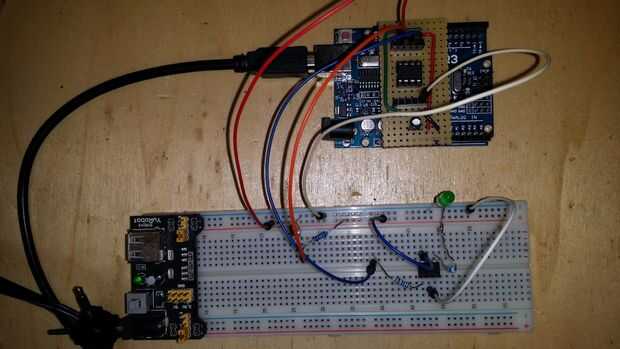
Para programar el ATTiny usted puede encontrar la instrucción en el ' ible en el paso anterior.
Este es el programa utiliza: (modificados en Consejo de gulliverrr)
/*ATTiny switch with timer (by Max Janssen june 2015)The ATTiny timer is not very accurate, but enough to switch for a certain number of secondsThe digital switch is based upon a LDR and resistor. GND---LDR---(A1)---100KOhm---5VThe switch output goes to an LH1540 Optocoupler Solid State Relais to switch whatever. Pin1---100Ohm---Pin1(LH1540)Pins 3 and 4 are used to jumper to GND and set different switching timesIf 3 phonecalls are received minimum 30 seconds and maximum 2 minutes apart the switch is triggered */ These constants won't change. They're used to give names // to the pins used: const int ldrValue = A1; // Analog input pin that the LDR is attached to const int setPin1 = 3; // for setting time delay const int setPin2 = 4; const int outputPin = 1; // to switch (ss relais)int sensorValue = 0; // value read from the LDR int timerValue = 0; int ldrTreshold = 600; //Treshold to switchvoid setup() { // initialize serial communications at 9600 bps (not for ATTiny) // Serial.begin(9600); pinMode(setPin1, INPUT_PULLUP); pinMode(setPin2, INPUT_PULLUP); pinMode(outputPin, OUTPUT); digitalWrite(outputPin, LOW); }void loop() { // read the LDR value: sensorValue = analogRead(ldrValue); if (sensorValue <= ldrTreshold) countRings(); // print the results to the serial monitor: /* Serial.print("Pin1 = " ); Serial.print(digitalRead(setPin1)); Serial.print(" Pin2 = " ); Serial.print(digitalRead(setPin2)); Serial.print(" sensor = " ); Serial.print(sensorValue); Serial.print(" timerValue = " ); Serial.println(timerValue); */ // wait before the next loop // for the analog-to-digital converter to settle // after the last reading: delay(200); }void countRings() { int ringCounter = 1; // phone has rung once unsigned long timeNow = millis(); delay(30000); //delay for 30 seconds while(millis() <= timeNow + 120000){ //check signal for 2 minutes sensorValue = analogRead(ldrValue); if (sensorValue <= ldrTreshold){ ringCounter = 2; break; } } if (ringCounter < 2) return; //the phone did not ring 2 times delay(30000); //delay for 30 seconds timeNow = millis(); while(millis() <= timeNow + 120000){ //check signal for 2 minutes sensorValue = analogRead(ldrValue); if (sensorValue <= ldrTreshold){ ringCounter = 3; break; } } if(ringCounter < 3) return; //the phone did not ring 3 times Switch(); // 3 rings => start the switching time } void Switch(){ // set timer value. set = 0, not set = 1!!! // setPin2, setPin1, delay (millisec) // 1 1 300.000 (15 min) // 1 0 1200.000 (30 min) // 0 1 3600.000 (60 min) // 0 0 7200.000 (120 min) int timerState = (digitalRead(setPin2)*10)+digitalRead(setPin1); // Serial.println(timerState); switch(timerState){ case 11: timerValue = 300000; break; case 10: timerValue = 1200000; break; case 1: timerValue = 3600000; break; case 0: timerValue = 7200000; break; } digitalWrite (outputPin, HIGH); delay(timerValue); digitalWrite (outputPin, LOW); } Cuando el programa de prueba puede disminuir la timerValue por lo que no tienes que esperar 2 horas para ver si funciona la última opción...
Debido al uso de INPUT_PULLUP puede puede conectar un puerto para conectar a tierra a nosotros como un interruptor. Por lo tanto el estado apagado es 1 y el estado es 0. (véase el uso de setPin1 y setPin2)
El ldrTreshold puede determinarse por subir el sketch a un Arduino Uno y usando la conexión en serie para mirar los valores. Estos valores pueden utilizarse en el ATTiny.
Por supuesto puede cambiar los valores de timerValue para adaptarse a su necesidad por los retrasos.
