Paso 11: Juntándolo todo
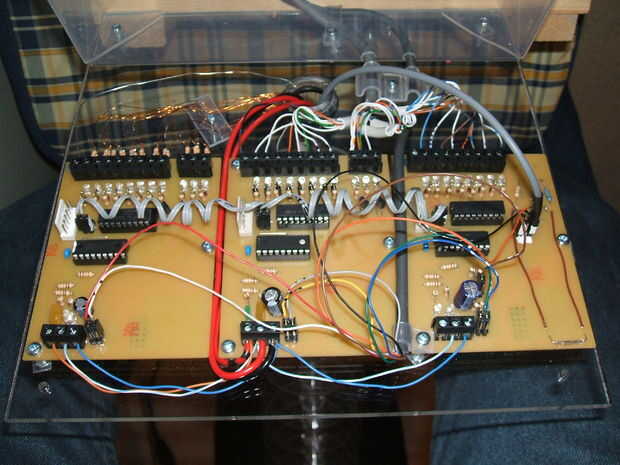
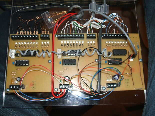
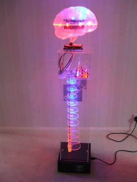
Una breve idea de la secuencia de eventos:
Cuando se aplica energía a las tres tablas de la derecha Junta inicia pulso lento de un conjunto de LEDs rojos en forma de latido del corazón. Esto se hace mediante software PWM comandos (parte de la suite gran vaca básica) para variar el brillo de un conjunto de LEDs de color rojo. Este código está en un bucle continuo.
Dependiendo de la configuración de los puentes, las otras dos tablas no hacen nada, solo bucle ronda esperando una señal que indica que el disco duro ha sido visitado.
Todos los tres tableros reaccionan cuando se recibe una señal para indicar que el disco duro ha sido visitado. Cada tablero haciendo una secuencia de efectos de iluminación LED dura unos pocos segundos. Si el disco no obtiene acceso a otra vez, las juntas se remontan a su bucle estado de 'default'. Si el disco duro sigue acceder (esto sucede a menudo) entonces siguen iluminación LED. La primera tabla mantiene un contador de tiempo pasando y si el disco duro ha sido repetidamente acceso durante un periodo de 30 segundos o más, entonces un 'más frenético' conjunto de efectos de iluminación LED activa y un segundo cable de señal comunica esta situación a los otros dos tableros para hacerles aumentar el tempo de sus efectos de LED.
Los "efectos de LED" incluyen:
- 'Rotar' patrón de LEDs en el maniquí plato de disco duro
- 'Movimiento' patrón de LEDs que viajan por la espina dorsal
- Flashes aleatorios de LEDs dentro de 'el cerebro'
Sólo por causa de interés, yo he reproducido el programa gran Basic de la vaca que es compilado y cargado en un PIC 16F88 para dar un sabor de lo que parece el elemento de software de este proyecto. Esta mucho más accesible que los métodos de programación de PIC normales. Algo similar se carga en cada uno de los tres módulos de PCB. Gran parte del código es comentario, en lugar de código activo. Cualquier cosa después de un apóstrofo es un comentario. Comentar es muy importante para el mantenimiento de software y este es un ejemplo de mi código de trabajo - no especialmente comentado para que otros puedan leer!
'Program which drives the "Brain" board (Kicad "LED driver module 01")' it has all of the PortB outputs connected to a ULN2804 driver ' it has PortA.4, PortA.6 and PortA.7 connected to MOSFET drivers ' it has PortA.2 (jumper 0) and PortA.3 (jumper 1)connected as mode jumpers (normally high - jumpers pull low) ' it has PortA.1 and PortA.0 as inputs ' it has no external connection to PortA.5 (pulled high and connected for Vpp)' The software consists of a 41 stage For/Next loop ' which drives the red 'heartbeat'. ' If a demand is made on the hard drive (ie PortA.0 has been driven high by the master board) ' then the blue leds on the dummy hard drive are lit alongside (ie as part of) the ' for/next loop. ' For the dummy hard drive leds to start, the for/next loop has to finish its heartbeat cycles. ' Hence there is a delay before the dummy drive lights start up.' The software uses a software PWM (RB1)'Program options'Hardware settings #chip 16F88, 8 'PIC 16F88 running at 8 MHz #config MCLR = Off, osc=INTRC_IO 'Turn off MCLR, select internal osc. 'WDT and LVP are disabled automatically'Initialise 'HEARTBEAT '~~~~~~~~~ 'Split waveform into 20 values to indicate the brightness of the red leds 'dim = 0 Bright = 60??? Table RedLedBrightness 3 3 2 2 2 2 2 10 30 50 70 90 100 100 100 100 100 100 100 100 90 80 70 60 55 50 45 40 35 30 25 20 15 10 5 5 4 4 3 3 end table'SET PORT DIRECTIONS Dir PORTB Outdir PORTA.4 out dir PORTA.6 out dir PORTA.7 out dir PORTA.0 in 'input line - demand being made dir PORTA.1 in 'input line dir PORTA.2 in 'mode jumper dir PORTA.3 in 'mode jumperdir PORTA.5 in 'MCLR connected to pin A5 - not used' next line sets up the software PWM channel #define PWM_Out1 PORTA.7'Set initial state of port B PORTB = b'10000000'set PORTA.4 off set PORTA.6 off set PORTA.7 offwait 2 s ' give the programmer a moment to kick in AllLedsOff'###################################################### 'Software PWM 'PWMOut channel, duty cycle, cycles in 0.5us cycles (for an 8MHz chip) ' , 0-255 , 100 = 50us 'not convinced about the 255 value being 100% ! Using 0 - 100 seems to cover the full brightness range??? '###################################################### 'Main routineDemandMade=falseDo'##### Check for jumper positions '================================ modeLSB=PORTA.2 ' jumper nearest to the power block modeHSB=PORTA.3 ' jumper away from the power block mode = modeLSB+(modeHSB*2)'no jumpers = 3 'jumper A.3 in = 2 'On user instruction - referred to as "J5 in J6 out (2): High demand causes random flashing of the blue lights." 'jumper A.2 in = 1 'On user instruction - referred to as "J5 out J6 in (1): High demand is ignored. Heartbeat and dummy disc are normal, blue plate lights off." 'both jumpers in = 0 'On user instructions - referred to as "J5 in J6 in: High demand causes dummy disc, red heartbeat and blue plate lights to randomly flash." 'REMEMBER jumper positions in the user guide are numbered in reverse 'to the markings on the physical wires (wire 1 = jumper 8, etc) '#### Check for demand and demand level '====================================== if Porta.0=on then DemandMade=true else DemandMade=false end ifif PORTA.1=on then PeakDemand=true else PeakDemand=false end if'#### Do the code required by the jumper position '================================================ Select case mode case 3 ' no jumpers in 'PORTB is sequenced in a circle for normal demand levels and sparkles for high levels 'Red LEDs have heartbeat in all circumstances 'Other 2 outputs have random sparkling at high levels - otherwise off if DemandMade=true then PORTB = b'10000000' For cycle = 1 to 40 ReadTable RedLedBrightness, cycle, brightness PWMOut(1, brightness , 25) if DemandMade=true and PeakDemand=False then Rotate PORTB Right simple if DemandMade=true and PeakDemand=True then PORTB = random ' makes output leds 'sparkle' PORTA.4=random/128 ' just a random 0 or 1 value PORTA.6=random/128 end if next case 1 'PORTB is sequenced in a circle for All demand levels 'Red LEDs have heartbeat in all circumstances 'Other 2 outputs are off off if DemandMade=true then PORTB = b'10000000' For cycle = 1 to 40 ReadTable RedLedBrightness, cycle, brightness PWMOut(1, brightness , 25) if DemandMade=true then Rotate PORTB Right simple next case 2 'PORTB is sequenced in a circle for all demand levels 'Red LEDs have heartbeat in all circumstances 'Other 2 outputs have random sparkling at high levels - otherwise off if DemandMade=true then PORTB = b'10000000' For cycle = 1 to 40 ReadTable RedLedBrightness, cycle, brightness PWMOut(1, brightness , 25) if DemandMade=true then Rotate PORTB Right simple if DemandMade=true and PeakDemand=True then PORTA.4=random/128 ' just a random 0 or 1 value PORTA.6=random/128 end if next case 0 'both jumpers in 'PORTB is sequenced in a circle for normal demand levels and sparkles for high levels 'Red LEDs have heartbeat unless there is high demand 'Other 2 outputs have random sparkling at high levels - otherwise off if DemandMade=true then PORTB = b'10000000' For cycle = 1 to 40 if DemandMade=true and PeakDemand=False then Rotate PORTB Right simple ReadTable RedLedBrightness, cycle, brightness PWMOut(1, brightness , 25) end if if DemandMade=true and PeakDemand=True then ' All ports just flash randomly 40 TIMES ' Great for MAXED-OUT brain (bright and vibrant!) PORTB = random ' makes output leds 'sparkle' if random>128 then set PORTA.4 on else set PORTA.4 off end if if random>128 then set PORTA.6 on else set PORTA.6 off end if if random>128 then set PORTA.7 on else set PORTA.7 off end if wait 40 ms end if if DemandMade=False then ReadTable RedLedBrightness, cycle, brightness PWMOut(1, brightness , 25) end if next end selectAllLedsOffLoop '###################################################### Function AllLedsOffPORTB = b'00000000' set PORTA.4 off set PORTA.6 off set PORTA.7 offend function

![Fijar el disco duro externo acceso denegado [SOLUCIONADO] Fijar el disco duro externo acceso denegado [SOLUCIONADO]](https://foto.askix.com/thumb/170x110/c/a1/ca1fc823404ca16cf18a7f97fc8e808d.jpg)

