Paso 6: El osciloscopio
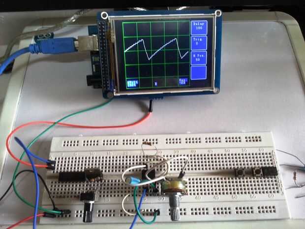
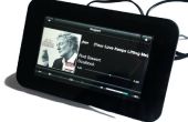
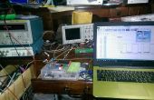
A continuación, encontrará el bosquejo para el osciloscopio. Antes de copiar y pegar el programa, vamos a revisar algunas limitaciones y explicar el programa.
He tenido que hacer una gran cantidad de investigación con el código, y muchos fragmentos han sido "prestados" de varias fuentes.
Divide el programa en varios subrutines para que sea más fácil de entender. El código está bien documentado, pero si tienes problemas para entenderlo, deje un comentario y yo voy a intentar explicarlo.
El ancho de banda del osciloscopio está limitada a aproximadamente 1 khz, pero hay margen de mejora.
La entrada es limitada a una forma de onda de pico a pico de 5 voltios, a menos que utilice un divisor del voltaje en la entrada y también limitada a formas de onda positivas de 0 a 5 voltios.
He utilizado algunos código que encontré en: http://www.microsmart.co.za/technical/2014/03/01/advanced-arduino-adc/ para ajustar el tiempo de la muestra de ADC.
Las funciones de gráficos y táctiles fueron modificadas y prestadas, de los ejemplos de Henning Karlsen en sus bibliotecas.
Utilicé un regulador de voltaje LM 317 y un temporizador IC 555 como un astable generados, para crear las señales utilizadas para comprobar la entrada del osciloscopio.
Esperamos que hayan disfrutado leyendo y esperamos construir este instructable. Si le resulta útil, por favor, vote por mí en los concursos.
Nota: Incluí el bosquejo, el UTFT y las bibliotecas de UTouch en el archivo libraries.zip para los problemas.
Copiar y pegar el bosquejo para el IDE de Arduino
---INICIAR PROGRAMA
/*--------------------------------------------------------------
Programa: OscopetouchLCDmega
Descripción: Osciloscopio Digital datos
en Color TFT LCD con pantalla táctil
Hardware: sainsmart mega2560 con 3.5" módulo tft lcd táctil pantalla y escudo kit
http://www.sainsmart.com/Home-page-View/sainsmart...
Software: Desarrollado utilizando el software de Arduino 1.0.3
Este programa requiere la biblioteca UTFT y el
UTouch biblioteca de Henning Karlsen.
Web: http://www.henningkarlsen.com/electronics
Versión 1.00
Fecha: 05 de abril de 2014
Autor: johnag
--------------------------------------------------------------*/
#include
#include
Declarar qué fuentes vamos a usar
extern uint8_t SmallFont [];
Inicializar la pantalla y tocar las funciones
UTFT myGLCD(ITDB32S,38,39,40,41);
UTouch myTouch(6,5,4,3,2);
Declarar variables
char buf [12];
int x, y;
int entrada = 0;
byte muestra [320];
byte OldSample [320];
int StartSample = 0;
int EndSample = 0;
int Max = 100;
int minutos = 100;
int modo = 0;
Tiempo de int = 1;
int tmode = 0;
int disparo = 0;
int SampleSize = 0;
int SampleTime = 0;
int dgvh;
Posh int = 50; conjunto 0v en rejilla horizontal
vsens int = 4; sensibilidad vertical
Definir varios prescaler de ADC
const unsigned char PS_16 = (1 << ADPS2);
const unsigned char PS_32 = (1 << ADPS2) | (1 << ADPS0);
const unsigned char PS_64 = (1 << ADPS2) | (1 << ADPS1);
const unsigned char PS_128 = (1 << ADPS2) | (1 << ADPS1) | (1 << ADPS0);
---Subrutines Inicio---
---drenaje sub botones
void buttons() {}
myGLCD.setColor (0, 0, 255);
myGLCD.fillRoundRect (250, 1, 310, 50);
myGLCD.fillRoundRect (250, 55, 310, 105);
myGLCD.fillRoundRect (250, 110, 310, 160);
myGLCD.fillRoundRect (250, 165, 310, 215);
}
sub de posición---pantalla táctil
void touch() {}
mientras (myTouch.dataAvailable())
{
myTouch.read();
x=myTouch.getX();
y=myTouch.getY();
Delay(500);
Si ((y > = 1) & & (y < = 50)) / / Delay fila
{
Si ((x > = 250) & & (x < = 300)) / / botón de retardo
waitForIt (250, 1, 310, 50);
Mode = modo ++;
{
myGLCD.setColor (255, 0, 0);
myGLCD.drawRoundRect (250, 1, 310, 50);
Seleccionar tiempos de retardo
Si (modo == 0) tiempo = 0;
Si (modo == 1) tiempo = 1;
Si (modo == 2) tiempo = 2;
Si (modo == 3) tiempo = 5;
Si (modo == 4) tiempo = 10;
Si (modo == 5) tiempo = 20;
Si (modo == 6) tiempo = 30;
Si (modo == 7) tiempo = 50;
Si (modo == 8) tiempo = 100;
Si (modo == 9) tiempo = 200;
Si (modo == 10) tiempo = 500;
Si el modo (modo > 10) = 0;
}}
Si ((y > = 70) & & (y < = 120)) / / mecanismo del disparador fila
{
Si ((x > = 250) & & (x < = 300)) / / botón de disparo
waitForIt (250, 55, 310, 105);
TMODE = tmode ++;
{
myGLCD.setColor (255, 0, 0);
Seleccione el valor de activación de Software
myGLCD.drawRoundRect (250, 55, 310, 105);
Si (tmode == 1) Trigger = 0;
Si (tmode == 2) gatillo = 10;
Si (tmode == 3) gatillo = 20;
Si (tmode == 4) gatillo = 30;
Si (tmode == 5) gatillo = 50;
Si (tmode > 5) tmode = 0;
}}
Si ((y > = 130) & & (y < = 180)) / H posición fila
{
Si ((x > = 250) & & (x < = 300)) / / H posición del botón
waitForIt (250, 110, 310, 160);
Posh = Posh ++;
{
myGLCD.setColor (255, 0, 0);
myGLCD.drawRoundRect (250, 110, 310, 160);
myGLCD.clrScr();
Buttons();
Si Posh (Posh > 60) = 50;
}}}}
---Espere toque sub
void waitForIt (int x1, int y1, int x2, int y2)
{
mientras (myTouch.dataAvailable())
myTouch.read();
}
---drenaje sub red
void DrawGrid() {}
myGLCD.setColor (0, 200, 0);
para (dgvh = 0; dgvh < 5; dgvh ++) {}
myGLCD.drawLine (dgvh * 50, 0, dgvh * 50, 240);
myGLCD.drawLine (0, dgvh * 50, 245, dgvh * 50);
}
myGLCD.drawLine (245 0 245, 240);
myGLCD.drawLine (0, 239, 245, 239);
myGLCD.setColor (255, 255, 255);
myGLCD.drawRoundRect (250, 1, 310, 50);
myGLCD.drawRoundRect (250, 55, 310, 105);
myGLCD.drawRoundRect (250, 110, 310, 160);
myGLCD.drawRoundRect (250, 165, 310, 215);
}
---Espera de entrada mayor que sub de gatillo
{} void trigger()
mientras (entrada < gatillo) {entrada = analogRead (A0) * 5/100;
}}
---Subrutines fin---
void setup() {}
myGLCD.InitLCD();
myGLCD.clrScr();
myTouch.InitTouch();
myTouch.setPrecision(PREC_MEDIUM);
Buttons();
pinMode (0, entrada);
configurar el ADC
ADCSRA & = ~ PS_128; quitar de la biblioteca Arduino
puede elegir un prescaler desde abajo.
PS_16, PS_32, PS_64 o PS_128
ADCSRA | = PS_64; establecer nuestro propio prescaler
}
void loop() {}
{while(1)}
DrawGrid();
Touch();
Trigger();
Recoger los datos analógicos en una matriz
StartSample = micros();
para (int xpos = 0;
XPOS < 240; XPOS ++) {muestra [xpos] = analogRead (A0) * 5/102;
delayMicroseconds(dTime);
}
EndSample = micros();
Mostrar los datos analógicos recopilados de matriz
para (int xpos = 0; xpos < 239;
XPOS ++)
{
Borrar pantalla anterior
myGLCD.setColor (0, 0, 0);
myGLCD.drawLine (xpos + 1, 255-OldSample [xpos + 1] * vsens Posh, xpos + 2, 255-OldSample [xpos + 2] * vsens Posh);
Si (xpos == 0) myGLCD.drawLine (xpos + 1, 1, xpos + 1, 239);
Dibujar los nuevos datos
myGLCD.setColor (255, 255, 255);
myGLCD.drawLine (xpos, 255-muestra [xpos] * vsens Posh, xpos + 1, 255-muestra [xpos + 1] * vsens Posh);
}
Determinar el voltaje pico a pico de la muestra
Max = muestra [100];
Min = muestra [100];
para (int xpos = 0;
XPOS < 240; XPOS ++)
{
OldSample [xpos] = muestra [xpos];
Si (muestra [xpos] > Max) Max = muestra [xpos];
Si (muestra [xpos] < Min) Min = muestra [xpos];
}
Mostrar el tiempo de la muestra, tiempo de retardo y desencadenar a nivel
myGLCD.setBackColor (0, 0, 255);
myGLCD.setFont (SmallFont);
myGLCD.setBackColor (0, 0, 255);
myGLCD.print ("retardo", 260, 5);
myGLCD.print ("", 270, 20);
myGLCD.print (itoa (tiempo, buf, 10), 270, 20);
myGLCD.print ("Trig.", 260, 60);
myGLCD.print ("", 270, 75);
myGLCD.print (itoa (Trigger, buf, 10), 270, 75);
myGLCD.print ("H pos.", 260, 120);
myGLCD.print (itoa (Posh, buf, 10), 270, 135);
myGLCD.setBackColor (0, 0, 0);
SampleTime = (EndSample-StartSample) / 1000;
myGLCD.print ("seg.", 205, 210);
myGLCD.print ("", 280, 30);
myGLCD.print (itoa (SampleTime, buf, 10), 205, 220);
Rango de 0 a 64 * 78 = 4992 mV
SampleSize = (Max-Min) * 78;
myGLCD.print ("mVolt", 5, 210);
myGLCD.print (itoa (SampleSize, buf, 10), 5, 220);
myGLCD.print (itoa (analogRead (A0) * 4.15 / 10.23, buf, 10), 110, 220);
}}
---FIN PROGRAMA
