Paso 2: Desarrollo y programación de Arduino
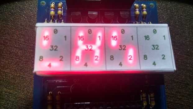
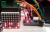
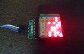
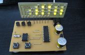
1) versión con Módulo LED Display (utilizados durante el desarrollo de componentes opcionales)
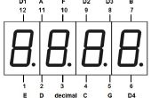
Para acelerar el desarrollo he utilizado el material opcional aparece antes en un conjunto con el módulo de pantalla con FYQ-5642AX LED pantalla.
Me gusta el tamaño de esta pantalla porque es más fácil de ver.
Con el módulo de LED que he creado es más fácil montar esta versión de prototipo.
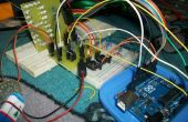
Sin ella tengo que poner en un protoboard muchos otros componentes como el shift register 74HC595 y muchas resistencias y cables para conectar todo.
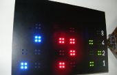
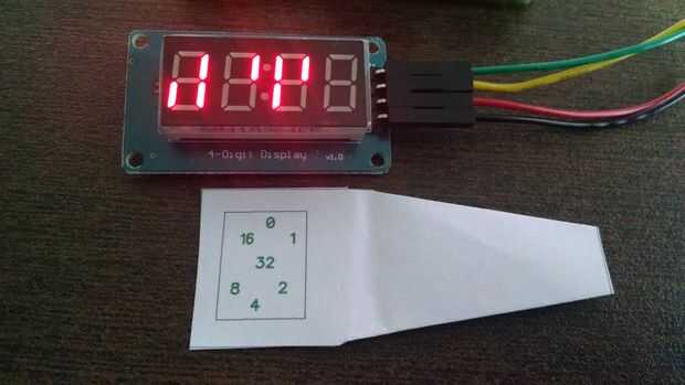
Nota: Puede ver el Video de esta configuración con un patrón (máscara) sobre la pantalla con los números para facilitar la lectura hasta que estés más Aeropuerto-hospedaje y confortable para la lectura de la pantalla sin él.
- Programación de Arduino (versión del módulo de pantalla)
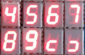
/* Binary Clock with Multiple LED Display Module - V1.0 LED Display - 4 Digits x 7 Segments by LAGSILVA - 10.June.2016 */int clockPin = 8; // Pin 8 of Arduino connected in the pin 11 of 74HC595 (Clock) int latchPin = 9; // Pin 9 of Arduino connected in the pin 12 of 74HC595 (Latch) int dataPin = 10; // Pin 10 of Arduino connected in the pin 14 of 74HC595 (Data)int PWMPin = 11; // Pin 11 of Arduino connecte do pin PWM to control the Brightness of Displayint hh, mm, ss; unsigned long ti;// A // ------ // | | // F | | B // | G | // ------ // | | // E | | C // | D | // ------// 0 // ------ // | | // 16 | | 1 // | 32 | // ------ // | | // 8 | | 2 // | 4 | // ------void setup() { pinMode(latchPin, OUTPUT); // Define the 3 digital pins (Latch-Clock-Data) as output pinMode(clockPin, OUTPUT); pinMode(dataPin, OUTPUT); pinMode(PWMPin, OUTPUT); hh = 16; //Initial setup of hours mm = 17; //Initial setup of minutes}void loop() { for (ss = 0; ss <= 59; ss++) { ti = millis(); // Initial time for the Timer of Hour/Time while ((millis() - ti) < 1000) { //analogWrite(PWMPin, 10); //Ajusta o brilho do display via entrada PWM (0 a 255 = 100% a 0% de brilho) // Plot Hours (hh) digitalWrite(latchPin, LOW); shiftOut(dataPin, clockPin, LSBFIRST, ~B10000000); //Set DISPLAY 1 shiftOut(dataPin, clockPin, LSBFIRST, 0); if (hh == 0) { shiftOut(dataPin, clockPin, MSBFIRST, 1); } else { shiftOut(dataPin, clockPin, MSBFIRST, hh << 1); } digitalWrite(latchPin, HIGH); // Plot Minutes (mm) digitalWrite(latchPin, LOW); shiftOut(dataPin, clockPin, LSBFIRST, ~B01000000); //Set DISPLAY 2 shiftOut(dataPin, clockPin, LSBFIRST, 0); if (mm == 0) { shiftOut(dataPin, clockPin, MSBFIRST, 1); } else { shiftOut(dataPin, clockPin, MSBFIRST, mm << 1); } digitalWrite(latchPin, HIGH); // Plot Seconds (ss) digitalWrite(latchPin, LOW); shiftOut(dataPin, clockPin, LSBFIRST, ~B00100000); //Set DISPLAY 3 shiftOut(dataPin, clockPin, LSBFIRST, 0); if (ss == 0) { shiftOut(dataPin, clockPin, MSBFIRST, 1); } else { shiftOut(dataPin, clockPin, MSBFIRST, ss << 1); } digitalWrite(latchPin, HIGH); } } mm = mm + 1; if (mm > 59) { mm = 0; hh = hh + 1; if (hh > 23) { hh = 0; } }} Nota: La máscara impresa se une en este paso es para FYQ-5642A LED pantalla. Sólo imprimir, cortar el papel y poner sobre la pantalla.
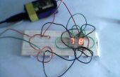
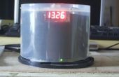
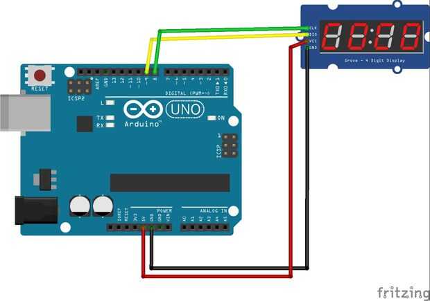
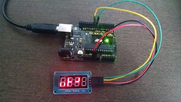
2) versión con pantalla de LED Catalex (TM1637)
En esta versión usé un display serial Catalex con ninguna máscara.
Nota: Los esquemas también están disponibles en este paso.
- Programación de Arduino (TM1637 - Catalex pantalla)
/* Digital Clock Binary Clock with 7 Segments Display - TM1637 (4 Digits x 7 Segments) by LAGSILVA - V1.0 - 10.Jun.2016 */#include // Module connection pins (Digital Pins) #define CLK 8 //Arduino Conection on Pin #8 = CLK of Display Module #define DIO 9 //Arduino Conection on Pin #9 = DIO of Display Module// // A // ---- // F | | B // - G- // E | | C // ---- // D // // 0 // ---- // 16 | | 1 // -32- // 8 | | 2 // ---- // 4 //uint8_t data[] = { 0, // data[0] for Hours 0, // data[1] for Minutes 0, // data[2] for Seconds};int hh, mm, ss; unsigned long ti;TM1637Display display(CLK, DIO);void setup() { display.setBrightness (0x0a);//(0x0f) is the max brightness; hh = 10; //Initial setup of Hours mm = 55; //Initial setup of Minutes}void loop() { for (ss = 0; ss <= 59; ss++) { // Plot Hours (hh) for (int k1 = 0; k1 <= 7; k1++) { if (bitRead(hh, k1) == 1) { bitWrite(data[0], k1 + 1, 1); } else { bitWrite(data[0], k1 + 1, 0); } } if (hh == 0) { bitWrite(data[0], 0, 1); } else { bitWrite(data[0], 0, 0); } display.setSegments(data + 0, 1, 0); // Plot Minutes (mm) for (int k1 = 0; k1 <= 7; k1++) { if (bitRead(mm, k1) == 1) { bitWrite(data[1], k1 + 1, 1); } else { bitWrite(data[1], k1 + 1, 0); } } if (mm == 0) { bitWrite(data[1], 0, 1); } else { bitWrite(data[1], 0, 0); } display.setSegments(data + 1 , 1, 1); // Plot Seconds (ss) for (int k1 = 0; k1 <= 7; k1++) { if (bitRead(ss, k1) == 1) { bitWrite(data[2], k1 + 1, 1); } else { bitWrite(data[2], k1 + 1, 0); } } if (ss == 0) { bitWrite(data[2], 0, 1); } else { bitWrite(data[2], 0, 0); } display.setSegments(data + 2 , 1, 2); delay(980); //Not exactly 1 second due the compesantion for processing time } mm = mm + 1; if (mm > 59) { mm = 0; hh = hh + 1; if (hh > 23) { hh = 0; } }} 3) el tiempo de configuración
Las siguientes declaraciones en el programa se utilizan para la configuración de hora y minutos.
Sólo ajustar antes de compilar el programa a Arduino como se muestra en este ejemplo:
hh = 16; //Initial setup of hoursmm = 17; //Initial setup of minutes
