Paso 2: Escribir el código ensamblador
Escriba el código siguiente en un archivo de texto llamado pushbutton.asm y compílelo con avra como hiciste en el Tutorial 1.
Observe que en este código tenemos un montón de comentarios. Cada vez que el ensamblador ve un punto y coma saltará el resto de la línea y pasar a la siguiente línea. Es buena práctica (sobre todo en lenguaje ensamblador!) de programación fuertemente comentar su código para que cuando vuelvas a él en el futuro se sepa lo que estaba haciendo. Voy a cosas de comentario bastante en la primera algunos tutoriales para que sepamos exactamente lo que está sucediendo y por qué. Posteriormente una vez que nos volvemos un poco mejores en el conjunto de codificación comentare cosas un poco menos detalladamente.
;************************************ ; written by: 1o_o7 ; date: <2014|10|23> ; version: 1.0 ; file saved as: pushbutton.asm ; for AVR: atmega328p ; clock frequency: 16MHz ;************************************
; Program function:------------------------------ ; Turns on an led connected to PB0 (digital 0) ; when you push a button connected to PD0 ;----------------------------------------------- ; ; PB0 (normally 0V) -----> LED --> 220 Ohm ---> 5V ; ; PD0 (normally 5V) -----> Button ---> GND ;
.nolist .include "./m328Pdef.inc" .list
;============== ; Declarations .def temp =r16 ; designate working register r16 as temp
;================= ; Start of Program rjmp Init ; first line executed
;============ Init: ser temp ; set all bits in temp to 1's. out DDRB,temp ; setting a bit as 1 on the Data Direction I/O ; register for PortB, which is DDRB, sets that ; pin as output, a 0 would set that pin as input ; so here, all PortB pins are outputs (set to 1) ldi temp,0b11111110 ; load the `immediate' number to the temp register ; if it were just ld then the second argument ; would have to be a memory location instead out DDRD,temp ; mv temp to DDRD, result is that PD0 is input ; and the rest are outputs clr temp ; all bits in temp are set to 0's out PortB,temp ; set all the bits (i.e. pins) in PortB to 0V ldi temp,0b00000001 ; load immediate number to temp out PortD,temp ; move temp to PortD. PD0 has a pull up resistor ; (i.e. set to 5V) since it has a 1 in that bit ; the rest are 0V since 0's.
;====================== ; Main body of program: Main: in temp,PinD ; PinD holds the state of PortD, copy this to temp ; if the button is connected to PD0 this will be ; 0 when the button is pushed, 1 otherwise since ; PD0 has a pull up resistor it's normally at 5V out PortB,temp ; sends the 0's and 1's read above to PortB ; this means we want the LED connected to PB0, ; when PD0 is LOW, it sets PB0 to LOW and turn ; on the LED (since the other side of the LED is ; connected to 5V and this will set PB0 to 0V so ; current will flow) rjmp Main ; loops back to the start of Main
Observe que esta vez no sólo tenemos muchos mas comentarios en nuestro código, pero también tenemos una sección de encabezado que da alguna información sobre quién lo escribió, cuando fue escrito, qué tipo de controlador que fue escrito, e incluso he incluido un diagrama del circuito simple para mostrar cómo construir el circuito. El resto del código es también separado en secciones.
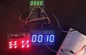
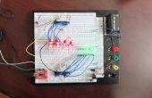
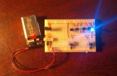
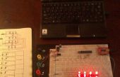
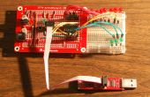
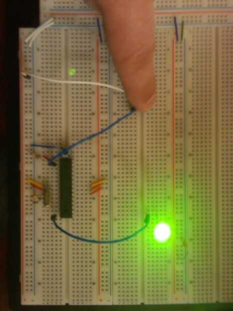
Después de haber compilado el código anterior debe cargarlo en el microcontrolador y ver que funciona. El LED debe encender mientras que están presionando el botón y luego apague otra vez cuando lo suelte. Me he mostrado como se ve en la foto.
