Paso 36: Software: configuración de Marlin
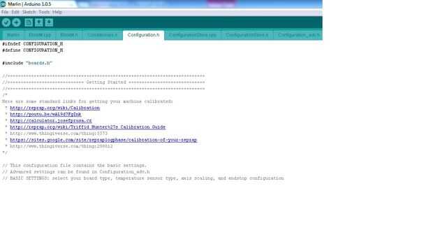
Esto es donde configuras el firmware en el Arduino para reflejar la configuración de la impresora. La configuración puede ser un poco abrumador en estos archivos de encabezado, pero la mayoría de ellos es opcional y las secciones están bastante bien documentadas Comentarios. (Puede localizar palabras clave en el IDE presionando Control-F para abrir el cuadro de diálogo 'Buscar')
Si no abre ya, vuelve a ejecutar el IDE de Arduino y abra el proyecto Marlin como se describe en el paso anterior.
Configuración de micropasos:
Cambie a la pestaña de Configuration_adv.h en el IDE y en cambio el ' ajuste de MICROSTEP_MODES para reflejar la configuración de jumper en la tarjeta de conductor rampas 1.4 - utilizamos 8 micropasos en todos los motores paso a paso:
// Microstep setting (Only functional when stepper driver microstep pins are connected to MCU. #define MICROSTEP_MODES {8,8,8,8,8} // [1,2,4,8,16] Los siguientes ajustes se encuentran en el archivo de encabezado Configuration.h y reflejan nuestra configuración de la impresora. Usted puede utilizar éstos como punto de partida, pero usted tendrá que personalizar dependiendo de su configuración, por ejemplo, si se utiliza 'Normalmente abierto' o 'Normalmente cerrado' fin detiene, el tamaño y el número de dientes en los engranajes, selección de termistor etc.
(Los valores aquí indicados sólo indica los valores cambiaron de los valores de instalación por defecto)
Selección de Junta:
// The following define selects which electronics board you have. // Please choose the name from boards.h that matches your setup #ifndef MOTHERBOARD #define MOTHERBOARD BOARD_RAMPS_13_EFB // EFB=Extruder, Fan & Bed #endif
Selección del termistor:
Hemos utilizado el 10 = RS termistor 198-961' en la extrusora y un 1 = EPCOS 100 k' en la climatizada imprimir cama.
//============================= Thermal Settings ============================ #define TEMP_SENSOR_0 10 #define TEMP_SENSOR_1 0 #define TEMP_SENSOR_2 0 #define TEMP_SENSOR_3 0 #define TEMP_SENSOR_BED 1
Topes:
Note que los topes máximo son definidos inicialmente, pero desactivados con la última entrada DISABLE_MAX_ENDSTOPS de #define.
//=========================================================================== //=============================Mechanical Settings=========================== //=========================================================================== // coarse Endstop Settings #define ENDSTOPPULLUPS // Comment this out (using // at the start of the line) to disable the endstop pullup resistors #ifdef ENDSTOPPULLUPS #define ENDSTOPPULLUP_XMAX #define ENDSTOPPULLUP_YMAX #define ENDSTOPPULLUP_ZMAX #define ENDSTOPPULLUP_XMIN #define ENDSTOPPULLUP_YMIN #define ENDSTOPPULLUP_ZMIN #endif // The pullups are needed if you directly connect a mechanical endswitch between the signal and ground pins. const bool X_MIN_ENDSTOP_INVERTING = true; // set to true to invert the logic of the endstop. const bool Y_MIN_ENDSTOP_INVERTING = true; // set to true to invert the logic of the endstop. const bool Z_MIN_ENDSTOP_INVERTING = true; // set to true to invert the logic of the endstop. const bool X_MAX_ENDSTOP_INVERTING = true; // set to true to invert the logic of the endstop. const bool Y_MAX_ENDSTOP_INVERTING = true; // set to true to invert the logic of the endstop. const bool Z_MAX_ENDSTOP_INVERTING = true; // set to true to invert the logic of the endstop. #define DISABLE_MAX_ENDSTOPS //#define DISABLE_MIN_ENDSTOPS
Ajustes del tope:
// ENDSTOP SETTINGS: // Sets direction of endstops when homing; 1=MAX, -1=MIN #define X_HOME_DIR -1 #define Y_HOME_DIR -1 #define Z_HOME_DIR -1 #define min_software_endstops true // If true, axis won't move to coordinates less than HOME_POS. #define max_software_endstops true // If true, axis won't move to coordinates greater than the defined lengths below. // Travel limits after homing #define X_MAX_POS 200 #define X_MIN_POS 0 #define Y_MAX_POS 200 #define Y_MIN_POS 0 #define Z_MAX_POS 200 #define Z_MIN_POS 0
Configuraciones del movimiento:
Los valores DEFAULT_AXIS_STEPS_PER_UNIT debe ser ajustada después de imprimir el bloque de calibración. También puede reducir la configuración de aceleración, especialmente cuando se usa una extrusora artesanal (valor E).
// default settings #define DEFAULT_AXIS_STEPS_PER_UNIT {45.5,45.9,4042,485} #define DEFAULT_MAX_FEEDRATE {500, 500, 5, 25} // (mm/sec) #define DEFAULT_MAX_ACCELERATION {9000,9000,100,10000} // X, Y, Z, E maximum start speed for accelerated moves. E default values are good for Skeinforge 40+, for older versions raise them a lot. #define DEFAULT_ACCELERATION 3000 // X, Y, Z and E max acceleration in mm/s^2 for printing moves #define DEFAULT_RETRACT_ACCELERATION 3000 // X, Y, Z and E max acceleration in mm/s^2 for retracts Configuración del LCD:
Asegúrese de descargar la biblioteca correcta (Arduino y no AVR) de https://bintray.com/olikraus/u8glib y extraerlo a la carpeta de las bibliotecas de Arduino.
// The RepRapDiscount FULL GRAPHIC Smart Controller (quadratic white PCB) // <a href="http://reprap.org/wiki/RepRapDiscount_Full_Graphic_Smart_Controller" rel="nofollow"> http://reprap.org/wiki/RepRapDiscount_Full_Graphi...</a> // // ==> REMEMBER TO INSTALL U8glib to your ARDUINO library folder: <a href="http://code.google.com/p/u8glib/wiki/u8glib" rel="nofollow"> http://reprap.org/wiki/RepRapDiscount_Full_Graphi...</a> #define REPRAP_DISCOUNT_FULL_GRAPHIC_SMART_CONTROLLER
Ahora puede compilar el código haciendo clic en el botón 'Verificar' en la barra de herramientas. Corregir los errores si, asegúrese de Repetier está desconectado del puerto serie y haga clic en el botón 'Subir' para copiar el archivo .hex en el Arduino.
