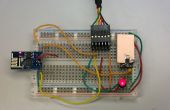
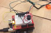
Paso 2: Sube tu dibujo!
Ahora puedes subir el bosquejo en su arduino y probarlo.
En este código LYT dirección es 0,0 y PL1167 chip select esta en pin 10 así que por favor cambiarlos en consecuencia a su configuración.
El nivel de sonido es continuamente en la entrada A0 y los picos de audio, tanto positivos como negativos, se calculan restando el valor de centro (340) el valor analógico leído y aplicando la función ABS (absoluta).
Si este valor va sobre el nivel del umbral SOUND_LEVEL un nuevos colores al azar es enviado a la LYT.
Esto generará variaciones en los sonidos graves.
/* * * * * * * * * * * * * * * * * * * * * * * * * * * * *<br> Code by AUTHOMETION S.r.l. Version: 1.00 Date: 02.06.2015 * * * * * * * * * * * * * * * * * * * * * * * * * * * * */ #include <SPI.h> #include <PL1167.h> #include <Lytwifi.h> #include <SoftwareSerial.h> #include <WiFiInterrupt.h> #define PL1167_CS_PIN 10 #define BULB_ADDRESS_HIGH 0 #define BULB_ADDRESS_LOW 0 #define SOUND_LEVEL 100
//ESP8266 Serial SoftwareSerial mySerial(5, 6); // RX, TX LYTWiFi myNetWork(mySerial);
void setup() { Serial.begin(115200, SERIAL_8N1); myNetWork.vfInitialize(PL1167_CS_PIN); vfISRInit(&myNetWork); //Initialize random generator randomSeed(analogRead(0)); } void loop() { int adc_sound; //POWER ON LYT myNetWork.ui8fSwitchOnAndCheck(BULB_ADDRESS_HIGH, BULB_ADDRESS_LOW, C_MULTICAST); delay(2000); while(1) { adc_sound=analogRead(0); //CONNECT MICROPHONE VCC TO ARDUINO 3.3 VDC FOR BETTER PERFORMANCE adc_sound=abs(adc_sound - 350);// Center on zero if(adc_sound>SOUND_LEVEL) { Serial.println(adc_sound); myNetWork.ui8fSetRGBValuesAndCheck(BULB_ADDRESS_HIGH, BULB_ADDRESS_LOW, random(255), random(255), random(255), C_MULTICAST); } } }
