Paso 5: Poner juntos todos
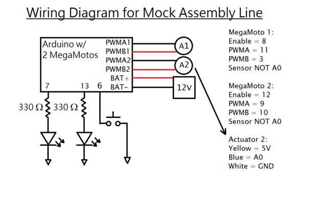
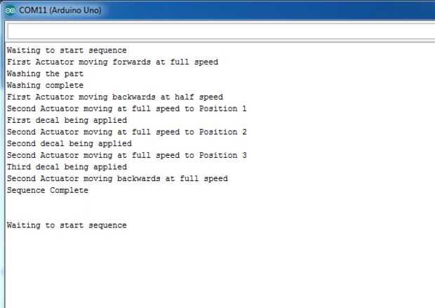
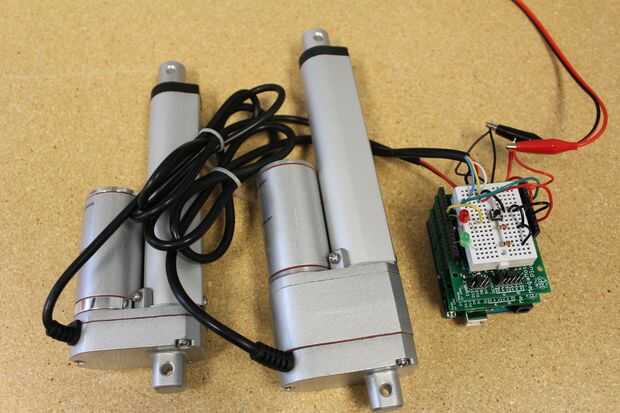
Puesto que ahora hemos visto todas las entradas y salidas en acción, vamos a poner todo junto!
Nos simulará una parte moviéndose a lo largo de una línea de montaje, con diferentes acciones que se aplica. Vamos a utilizar interruptores de límite y la retroalimentación del potenciómetro del actuador. Esta es la secuencia que seguiremos:
-Esperar a pulsar el botón de entrada para iniciar el ciclo
-Extender el primer actuador a toda velocidad por 5 segundos para mover la pieza en su lugar
-Enciende el LED para simular un ciclo de lavado se inicia
-Esperar 5 segundos para el lavado, luego apague el LED
-Retraer el primer actuador a media velocidad durante 10 segundos para secar la parte
-Extender el segundo actuador a toda velocidad hasta la posición 1
-Enciende el otro LED, esperar 2 segundos, apagar el LED
-Extender el segundo actuador a toda velocidad hasta la posición 2
-Enciende el otro LED, esperar 2 segundos, apagar el LED
-Extender el segundo actuador a toda velocidad a la posición 3
-Enciende el otro LED, esperar 2 segundos, apagar el LED
-Retire el actuador segundo a toda velocidad por 5 segundos para completar el ciclo.
-Esperar a pulsar el botón para reiniciar el ciclo de entrada
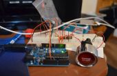
Cablee el sistema según el esquema y cargar el código para ver cómo funciona!
Ya que estos son solo programas de prueba, puede dejar el tablero conectado a la computadora para que el Arduino puede recibir energía.
/* This code is to show how outputs are used in a switch statement. The code moves an actuator in and out at varying speeds, according to the sequence. Written by Progressive Automations Sept 21, 2015 This code is in the public domain */ const int enable1 = 8; const int PWMA1 = 11; const int PWMB1 = 3;//pins for the first MegaMoto(Actuator) const int enable2 = 12; const int PWMA2 = 9; const int PWMB2 = 10;//pins for the second MegaMoto(Actuator) const int potFeedback = A0;//pin for the second actuators potentiometer const int LED1 = 7; const int LED2 = 13;//two pins for LEDs const int button = 6;//restart button int programCount = 0;//variable to move through the program int buttonState = 1;//vairable to store the state of the button,initialise as HIGH int pos1 = 100; int pos2 = 500; int pos3 = 1000;//three positions to move to void setup() { Serial.begin(9600);// initialize serial communication: programCount = 0;//start at the beginning pinMode(enable1, OUTPUT); pinMode(PWMA1, OUTPUT); pinMode(PWMB1, OUTPUT);//set first MegaMoto as outputs pinMode(enable2, OUTPUT); pinMode(PWMA2, OUTPUT); pinMode(PWMB2, OUTPUT);//set second MegaMoto outputs pinMode(LED1, OUTPUT); pinMode(LED2, OUTPUT);//set LED's as outputs pinMode(button, INPUT);//set button as input digitalWrite(button, HIGH);//enable internal pullup pinMode(potFeedback, INPUT);//set potentiometer as input }//end setup void loop() { switch (programCount) { case 0: digitalWrite(enable1,LOW); digitalWrite(enable2,LOW);//disable both control boards so the actuators cant move Serial.println("Waiting to start sequence"); while (digitalRead(button) == 1){}//wait here until button is pressed programCount = 1;//once button is pressed, advance break; case 1: digitalWrite(enable1, HIGH);//enable the first actuators control board Serial.println("First Actuator moving forwards at full speed"); analogWrite(PWMA1, 255); analogWrite(PWMB1, 0);//set the speed of the actuator delay(5000);//Move for 5 seconds analogWrite(PWMA1, 0); analogWrite(PWMB1, 0);//stop the actuator programCount = 2; break; case 2: Serial.println("Washing the part"); digitalWrite(LED1, HIGH);//turn on LED programCount = 3; break; case 3: delay(5000); Serial.println("Washing complete"); digitalWrite(LED2, LOW);//turn off LED programCount = 4; break; case 4: Serial.println("First Actuator moving backwards at half speed"); analogWrite(PWMA1, 0); analogWrite(PWMB1, 128);//set the speed of the actuator delay(10000);//Move for 10 seconds analogWrite(PWMA1, 0); analogWrite(PWMB1, 0);//stop the actuator programCount = 5; break; case 5: Serial.println("Second Actuator moving at full speed to Position 1"); digitalWrite(enable2,HIGH);//enable the second actuators control board while (analogRead(potFeedback) <= pos1) { analogWrite(PWMA2, 255); analogWrite(PWMB2, 0);//set the speed of the actuator } analogWrite(PWMA2, 0); analogWrite(PWMB2, 0);//stop the actuator programCount = 6; break; case 6: Serial.println("First decal being applied"); digitalWrite(LED2, HIGH); delay(2000); digitalWrite(LED2, LOW); programCount = 7; break; case 7: Serial.println("Second Actuator moving at full speed to Position 2"); while (analogRead(potFeedback) <= pos2) { analogWrite(PWMA2, 255); analogWrite(PWMB2, 0);//set the speed of the actuator } analogWrite(PWMA2, 0); analogWrite(PWMB2, 0);//stop the actuator programCount = 8; break; case 8: Serial.println("Second decal being applied"); digitalWrite(LED2, HIGH); delay(2000); digitalWrite(LED2, LOW); programCount = 9; break; case 9: Serial.println("Second Actuator moving at full speed to Position 3"); while (analogRead(potFeedback) <= pos3) { analogWrite(PWMA2, 255); analogWrite(PWMB2, 0);//set the speed of the actuator } analogWrite(PWMA2, 0); analogWrite(PWMB2, 0);//stop the actuator programCount = 10; break; case 10: Serial.println("Third decal being applied"); digitalWrite(LED2, HIGH); delay(2000); digitalWrite(LED2, LOW); programCount = 11; break; case 11: Serial.println("Second Actuator moving backwards at full speed"); analogWrite(PWMA2, 0); analogWrite(PWMB2, 255);//set the speed of the actuator delay(5000);//Move for 5 seconds analogWrite(PWMA2, 0); analogWrite(PWMB2, 0);//stop the actuator Serial.println("Sequence Complete"); Serial.println(""); Serial.println("");//print some blank spaces to make serial monitor more read-able programCount = 0;//loop back to the beginning break; default: Serial.print("Error"); while (1); //freeze the program here }//end switch }//end loop
